When it came to custom mechanical keyboards, it didn't take very long to understand why even a barebones Satisfaction 75 for $480 was vastly different from a mass-produced $20 Logitech keyboard & mouse combo. But with Merc Stealth being a membrane keyboard, everything had seemingly come full circle: there was no obvious technical reason why a mass-produced membrane keyboard in a plastic case should cost so much.
A Simple Commission
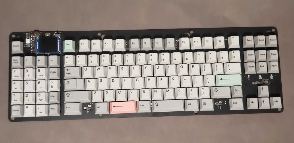
My journey with the Merc Stealth began in the spring of 2022, when I received an email from someone named Doug inquiring if I could make him a custom keyboard. He attached a keyboard layout that he generated using keyboard-layout-editor.com. He mentioned that his goal was to replace the gaming pad of his Merc Stealth keyboard (shown below), but he would like the replacement to have mechanical switches instead.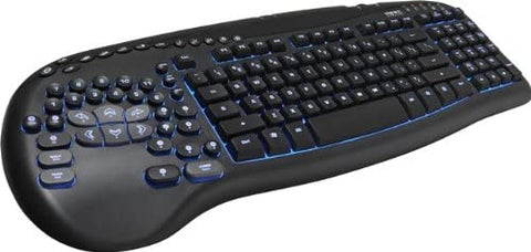


Almost a full year later, in March 2023, Doug emailed me a third time with another commission request. Although I had built the two previous keyboards precisely to his specification, he still felt the final result was not an ideal replacement for his Merc Stealth, so he had a radically different proposal. He wanted to send me one of his Merc Stealth keyboards so that I could convert the internals to become a mechanical keyboard. This approach--if viable--would virtually ensure that it had the same layout and feel as the original Merc Stealth.
At this point, I realized a few things:
- Doug was persistent; he would not rest until he had a suitable replacement for his Merc Stealth.
- His returning to me for a third time suggested that he was happy with my quality of work, yet unsatisfied with the product itself, meaning there was just a requirements problem and not a performance problem.
- If I was to have any chance of successfully replacing the guts of a Merc Stealth, I would need to understand the full scope of what it would entail: What was actually relevant? What made this layout so special? Why not just buy another Merc Stealth and be done with it?
To determine feasibility, I would need to examine a Merc Stealth up close, so I accepted his offer to ship one to me for evaluation, after which I could determine whether I could do the job. And even if I could do it, whether I would actually want to take it on.
Supply and Demand
While waiting for Doug's Merc Stealth to arrive, I did some research into the history of the keyboard. The Merc Stealth keyboard is a membrane keyboard originally made by Ideazon (called Zboard/Fang) that SteelSeries acquired and subsequently discontinued in 2013. From a supply and demand perspective, being discontinued ten years ago means that supply now in 2023 is extremely limited. Continued demand for a product in limited supply has resulted in astronomical pricing. Indeed, searching online you can find multiple online petitions from customers requesting SteelSeries to "bring back the Merc Stealth," and others who--like Doug--have tried to remake the layout as a mechanical keyboard.However, one critical feature of the gaming pad layout is that it uses a variety of small, sculpted, and closely-spaced keys. On a normal keyboard, when using the WASD keys for gaming, almost half of the number row keys are unreachable without moving the hand away from the WASD keys. In contrast, the Merc Stealth gaming pad enables eleven number row keys to be accessible from the WASD cluster.

While I fully anticipate that some readers will have no appreciation for this particular layout, it turns out that there are quite a few people who have used this gaming pad layout for upwards of ten to fifteen years, and they now refuse to use anything else. Their muscle memory is too well-formed, and the convenience of the full number row within reach is far too great.
From a purely technical standpoint, the Merc Stealth was somewhat underwhelming and problematic. Aside from being a membrane keyboard that wears out after a few years of heavy use, there are now driver compatibility issues with modern operating systems, and the keyboard itself only supports 4KRO (that is, four key rollover, so only up to four keypresses are detected at once).
Some people online speculate that the Merc Stealth layout couldn't be reproduced by others because it was patented; I searched the USPTO website and found no patents from either Ideazon or SteelSeries to substantiate this claim. This finding is consistent with my understanding that keyboard layouts are inherently not patentable (but I am not a patent attorney, so if I missed something and there actually is a relevant patent, please send the relevant patent number to sales@custommk.com).
Forming a Plan
Within a few days, Doug's Merc Stealth arrived, and I began to take it apart while taking measurements in earnest. First, I discovered that MX switch stems could fit (albeit loosely) inside the original keycap stems when rotated at a specific orientation. So it seemed that I could reuse the original keycaps, but I would need to glue or epoxy the keycaps onto switches.

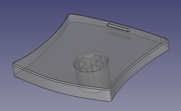
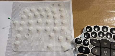
Because of the nonstandard key sizes and placement, there was no normal "1u" grid layout to follow. Locating each switch precisely--and at the correct orientation to fit in the keycap--would be a challenge. To overcome this problem, I generated a 1mm x 1mm grid and printed it on paper. I then laid the original Merc Stealth membrane on top of it, fixed it in place with pins, and poked pinholes through the membrane and grid paper at each of the switch centers. This gave me measurable coordinates for all the switch centers, which I could then plot and visualize to confirm the measurements. This also allowed me to 3D print a "faux PCB" to perform fit checks.

However, these fit checks revealed yet another problem: not only are the keycaps smaller than typical 1u keycaps, they are so small that I couldn't even fit MX switches underneath them. That is, even reusing the original keycaps, the MX switch housings would physically interfere with each other. This was a massive problem, because if you can't fix MX-style mechcanical switches, you can't really have a mechanical keyboard at all.
Switch of Theseus
As it turns out, there are many parts of a mechanical switch, and not all of them are important in every keyboard. Overall, the housing and clips hold the switch together (required), the stem attaches to the keycap (required), and the metal parts make electrical contact (required). But around the very edge of the housing are bits of plastic that help it clip into a switch plate. If you go with a plateless keyboard design, those bits of plastic are unnecessary. Likewise, there is a portion of the switch reserved for LEDs or light pipes for backlit keyboards. Since I wasn't planning to give ErgoStrafer per-key backlighting, this portion of the switch housing could also be removed.
Those two observations alone resulted in enough removable material that I could actually use a Dremel to cut down switches to fit in the tight space demanded by the layout.


After using the 3D printed faux PCB to confirm that the cut-and-rotated switches would fit, I started testing the keycap installation process, and once more, a new problem was discovered. When attaching keycaps to the switch stems, the adhesives required time to set, which meant holding them in the precisely correct position for a lengthy amount of time. Meanwhile, the adhesive also flowed into other parts of the switch, gumming them up and interfering with switch operation. After the adhesive had set, the outer diameter of the keycap stem ended up being too big for the switch to reliably actuate (the keycap stem could hit the top of the switch housing when pressed). Lastly, without good surface-to-surface contact area within the stem, the adhesion overall was poor, and the keycap would easily break off from the switch.
This was (again) a significant setback because neither of the backup options were ideal. For the first option, I could cut the stems from the original keycaps, and then cut off most of the keycap surface from normal MX keycaps. This would allow me to glue the Merc Stealth keycap surface onto an MX keycap stem, but that requires a lot of manual labor per keycap and introduces ample opportunities for alignment errors (the keycaps might not be centered or rotated correctly).
The other option--3D modeling and 3D printing each keycap--would take a lot of tedious work to do right. The keycaps are all sorts of odd shapes, with concave and convex surfaces, bevels, slants, and differing key heights. 3D printing the keycaps would also mean that ErgoStrafer would not have legends on the keycaps. But...3D printed keycaps would at least be consistently reproducible and require less hands-on labor. If I wanted to make additional ErgoStrafers, it would sidestep the need to scavenge original keycaps (which will likely be increasingly hard to find).
Ultimately, I chose to 3D model and 3D print the keycaps. That process is documented in a separate article which you can find here.
Case design and feature creep
Armed with 3D models of each keycap, I was able to more fully flesh out the entire assembly in FreeCAD by incorporating switch models and keycaps. At this point, because I had well-defined shapes and placement for each keycap, it seemed increasingly more reasonable to move away entirely from the concept of re-using the original Merc Stealth case and instead 3D print a dedicated case. So I decided to do that....and immediately stumbled into a few new problems to solve:
- I would need to accurately reproduce the tilt angles.
- The gamppad keys on the Merc Stealth are collectively rotated relative to the front edge of the keyboard, meaning that rotation would need to be measured and reproduced to create the tilt in the right direction.
- I would need to ensure the height of each key matches the original.
- The sloped wrist rest area near the game pad would need to be reproduced as well.
It was around this time I also had a few realizations and insights about the overall layout which helped to finalize all keycap and switch dimensions and rotations with greater certainty and precision. I discuss those topics in more detail in this article posted to the customMK Patreon. One nice side effect of that improvement was that it allowed me to effectively reset all the switch orientations to be consistent (aside from the top right keys which are rotated 10 degrees relative to the others) which helped to make the switch cutting process less random.


Diagram showing required switch cuts for ErgoStrafer
Prototype Sponsorship from PCBWay
In January 2023, I published an article about our Engikeeb experiments, which caught the attention of the folks at PCBWay. They graciously offered to sponsor our next project, and ErgoStrafer seemed like a good fit. So I took them up on their offer--not just for the PCB assembly, but also for all the 3D printed parts as well! I want to give a huge thank you and shout out to them for provding direct support for these innovative projects. PCBWay was very easy to work with and the parts all came out very nice!

Making ErgoStrafer Even Better than the Merc Stealth
Aside from switching to mechanical switches and eliminating driver issues by using QMK, I found other opportunities to optionally make ErgoStrafer even better than the original Merc Stealth:
- There is now an option for Z and X keys underneath the A and S keys. It re-uses the E and W key shapes, so it doesn't quite match up with the overall carveout for the other six keys, but it was a tradeoff between that and having unusually tall keys there instead. Having these two keys does require a different case design to support it, but the PCB is identical.
- The three round keys in the top right (Load, Print Screen, and Save) are 10mm in diameter and are taller than the rest of the keys. I realized that these are likely not used as often while gaming, so I decided to include an option to install rotary encoders in any (or all) of those three locations. The default function of the encoders is volume control, but they can be re-assigned to anything easily using VIA.
- Just for fun, I included a buzzer too, which can be programmed to make sounds. By default it just plays a few quick notes upon the keyboard being plugged in. This can be easily disabled in VIA or highly customized to play different sounds by recompiling custom firmware.
I decided to give EgroStrafer the same powerful hardware used in the open source Bonsai C4: a very fast ARM microcontroller running open source QMK firmware to scan for keypresses several thousand times per second. It also includes 8kB of FRAM for storing settings, which provides up to 32 layers of custom key assignments in VIA and plenty of room for custom macros. Also, the 4KRO limitation of Merc Stealth is replaced with NKRO, meaning that all the keys can be pressed and detected simultaneously.

ErgoStrafer VIA Screenshot
And the verdict is...
Because I hadn't personally owned and used a Merc Stealth, I was in no position to evaluate whether it actually met the goal of being able to replace it and fully satisfy Doug (and presumably anyone else using a Merc Stealth). After a few days of nervously waiting for the first ErgoStrafer shipment to get to Doug, I had my answer:
"It's even better than I expected, a flawless recreation of the Merc Stealth" -Doug

Doug was happy--I was happy.
With that feedback that it was a success, I added ErgoStrafer to the customMK product listings. While it is more expensive than I had hoped it would be (albeit nowhere near "$2k expensive"), it is because the parts are expensive and the touch labor is high. In particular, the case consumes a lot of 3D printer resin, and the assembly process requires manually cutting down switches by hand (or rather, a Dremel). To try to provide more affordable options, I've included both black and white 3D printed parts because for some reason the 3D printed white parts are lower cost.
I've also listed the most essential components--the PCB and keycaps--as items that can be purchased separately. This allows customers to avoid the expensive material cost of the case and eliminate my time and labor cutting down switches to fit and assembling the switches, keycap, and case.