Creating Multicolor 3D Prints with JLCPCB using Free Software
In this post we will provide an overview of the process we used to generate a multicolor 3D model of a keycap for use in JLCPCB’s full color 3D print services.
We used only free and/or open source tools, so Solidworks and Fusion 360 are unnecessary--but we did make use of 3D Builder which is freely included with Microsoft Windows. To save you time, here is a quick summary of our process:
- Use FreeCAD to create a parametric 3D model of the keycap and generate a 3D mesh
- Use FreeCAD to reshape the mesh to include the shape of the keycap legend
- Use Blender to apply a solid color to the legend
- Use Blender to apply an image wrap to the entire 3D model
- Use 3D Builder to generate the file format needed for upload to JLCPCB
- Use a zip compression tool to overcome an incompatibility between 3D Builder and JLCPCB import.

I’ll also explain a bit about the filetypes involved because it is actually pretty relevant and a source of potential problems.
For "bigger picture" context: customMK accepted a keyboard design commission earlier this year to reproduce the SteelSeries Merc Zboard gamepad layout as accurately as possible using mechanical keyboard switches:

We ended up creating (or re-creating?) 3D models for the keycaps and case, and we are having it all 3D printed. This is still a work in progress, as parts are currently being 3D printed. While it is not released yet, we have decided to call the product “ErgoStrafer" and we have an Interest Check for it here.


For this design, the keycaps are not standard MX keycaps, so creating 3D models of the keycaps from scratch was a necessary step in the process. We considered simply re-using the original keycaps, but they were not designed to fit the stems of MX switches (just FYI, the original keyboard was a membrane keyboard, not mechanical). We will be covering much more of the design process for this particular keyboard commission in future articles, but the focus of this article is specifically “how to add color to 3D models for 3D printing” (importantly, without buying expensive CAD software).
I should also mention that adding legends to the keycaps was *not* within the scope of the commissioned work. Our customer, Doug, is perfectly happy to receive blank keycaps because he already has over a decade of muscle memory trained on this layout. The reason we wanted to try to adding a legend is because….well, it seemed like a fun and interesting thing to do. If the result actually looks good, then this method can provide an alternative to producing full-color artisan keycaps without needing to hand painting them (so they are more consistent and less labor-intensive). However, full-color 3D printing is still rather expensive--comparable to artisan keycaps at "tens of dollars per keycap", so we’re only making one keycap for now to just flush out the kinks in the system and get to a proof of concept.
JLCPCB and File Formats for 3D Printing
JLCPCB offers a variety of 3D printing capabilities, one of them being full-color 3D prints. There are only a handful of 3D printer technologies capable of achieving this, but based on the material choices available it seems that JLCPCB may be using HP's color 3D printer technology, which was sadly discontinued last year.
To upload a 3D printable file for multicolor prints, there are a few additional requirements above and beyond normal 3D printing. Specifically, in addition to there being a watertight mesh of triangles (e.g. STL files for the past decade) to form the outside surface of the item, there must now be colors assigned to the surface as well. Traditional STL files fall short of this capability, because they do not contain color information. It is worth noting that colors are assigned to the surface mesh only, so color will only be applied to the outer surface of the 3D print.
JLCPCB requires that the uploads must be either 3MF format or OBJ format for full color 3D printing. 3MF is a relatively newer open standard that is intended to an "all-in-one" file for all kinds of 3D printing. The file format requires that the contents be a closed manifold (i.e. watertight), and it can also contain color and texture/image information within the 3MF file itself.
The OBJ file format has been around a little longer than 3MF, but interestingly OBJ doesn't actually store color or texture information internally. If you have colors assigned to faces or mesh triangles in your 3D modeling tool, then exporting to an OBJ file will not only create the OBJ file, but also create a MTL file (material file) as well, which contains surface color information. Also, if surface textures (i.e. images) are used, then a JPG file (or other image files) are created as well when the OBJ export happens. Thus, the OBJ file refers to an MTL file which can refer to a JPG (or multiple JPGs). You can see this process happen in reverse with some modeling software when importing an OBJ file—for example, upon importing an OBJ file with color, Microsoft's 3D Builder asks you to locate the MTL file (even if it's already in the same folder as the OBJ), and--if needed--will also ask you to locate the JPG file(s) as well.
Generating a 3D Mesh With Edges at Color Boundaries in FreeCAD
So with that context, when you try to search out information on how to add color to 3D models for 3D printing, the most common search results start with "Solidworks makes this very easy, all you have to do is..." but…..Solidworks is not free software, and I don't own it, so those search results are somewhat less than helpful. Fortunately, with a handful of free tools, you can still get the job done.
My starting point was FreeCAD, because that is my preferred CAD tool for parametric design. I won’t cover the overall keycap shape modeling in this article, so the starting point is “I have a keycap 3D model.” Once you have a 3D model in FreeCAD, you *could* export to an OBJ file immediately, but in my case, I also wanted to use FreeCAD to rearrange the surface mesh to provide the outline for the legend. That is, for the keycap I had precise placement of lettering/shapes that I wanted, which made sense to do in FreeCAD. We took the keycap 3D model and create two solid bodies--one for each desired surface color.
- I first created duplicate of the main 3D object (a custom keycap)
- I then created a sketch (or sketches) with the desired 2D surface shapes

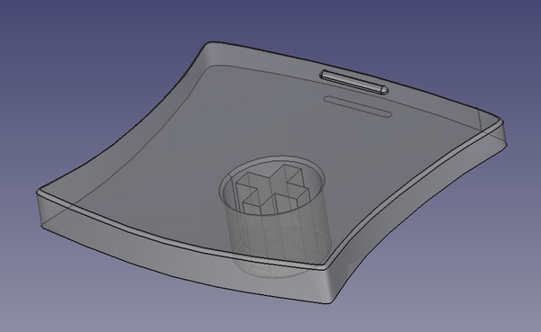
- I extruded the sketches to make them a separate solid that passes through the surface of the keycap. Note the presence of the "buried" piece touching each shape, which was done because FreeCAD requires each body to consist of a single solid piece of material.

- I then duplicated the solid object representing the legend shape
- Using the Parts workbench, I took a copy of the keycap and subtracted the solid legend from it, leaving a recessed area matching the shape of the legend. A black color was also assigned to the keycap (technically not required at this stage, but it helps with the visuals here)

- Using the Parts workbench, I took the copy the solid legend and performed an intersection with the keycap. This resulted in a solid that perfectly filled the recessed area created in the previous step, and which also matches the curvature of the original keycap surface. A white color was also assigned (again, not required at this stage, but helps with the visuals)

At this point, I had two solid objects: one was the original object with some material removed, the other was a shape to fill in the removed material. I used the Parts Workbench to union these together get back to the original shape, but now with the added distinction that the 3D mesh edges were guaranteed to exist at the boundary of the keycap legend:

To drive home the relevance of that distinction, let's convert both the original keycap (without legend) and this updated keycap (with legend) to a 3D mesh using FreeCAD's Mesh Design workbench:

You can see the original keycap mesh on the left is pretty straightforward, no surprises. But the keycap on the right that we took through the legend process now has a bunch of additional triangles dedicated to the legend shapes. The "S" in particular is readily observable here.
Adding Solid Colors and Image Wraps to the 3D Mesh in Blender
To make the mesh even more visible, we can export using Meshes -> Export Mesh, and save it as a 3MF or OBJ file. We can then open up Blender and import that file, which looks like this in Edit Mode:

Note that if you want to import/export the 3MF format with Blender, you will need to install the 3MF addon. In my experience, the 3MF format kept the size consistent, whereas the OBJ approach resulted in units being changed (mm to m), so a 1:1000 scaling transformation was required to correct it.
With the mesh now in Blender, we can do all sorts of fun Blender-y things like UV wrapping and assigning materials to each triangle of the mesh independently. Here is an example tutorial video showing how to add an image as a UV wrap to an object. Here is the process I used to apply color to the mesh:
- Add an initial material color (black) to the mesh overall.
- Then add a second material option, in my case, white.
- In edit mode, select all the triangles in the legend shape and assign the white material to the selected mesh triangles.

- Change the original black color to an image texture, in my case, a 2x2 carbon fiber image.
- Use the UV mapping tools to scale, rotate, and move the image applied to each face as desired. For this keycap, I focused on two objectives: accurately sizing the image to achieve a typical 3k 2x2 carbon fiber twill weave width of 0.125", and getting the top edges to match the sides so that it would appear to be a realistic carbon fiber wrap.

Preparing Files for Upload to JLCPCB using 3D Builder (and a zip/compression tool)
At this point, most of the hard work is done! The keycap is a complete mesh with the correct textures applied. Unfortunately, there seems to be some problem with the 3MF import/export addon for Blender, at least for me. So instead I exported to OBJ (which created an MTL and JPG file as well). As of May 2023, for color 3D prints, JLCPCB only lets you upload 3MF or OBJ files. They do not let you upload any MTL or JPG files, nor any zip file containing OBJ+MTL+JPG files. If we upload only OBJ files, there will be no colors or textures applied, which defeats the purpose of a full color 3D print. So 3MF is currently the only viable format for uploading full color 3D models to JLCPCB.
Also, fun fact: having a multicolor 3D printed keycap costs more than twice the cost of a full metal 3D printed keycap! Anything involving color printer ink always seems to have that sort of effect...while the cost to print is entirely unreasonable for normal keycaps, it at least appears to be somewhat in line with artisan keycap prices.
With the OBJ file exported, I then used Microsoft's 3D Builder to importe the OBJ (and related files) and then re-exported it to the 3MF format (because JLCPCB accepts the 3MF file format for multicolor 3D print uploading). I checked with several tools to ensure the file was good and complete. One of them was the HP SmartStream 3D Build Manager--because if that software can't open it, then an HP 3D printer is likely going to have problems as well. I also found https://3dviewer.net/ was useful for doing quick reality checks of the 3D models.
There was just one more step to do which is going to seem enitrely unnecessary, but…whenever I uploaded my 3MF file to JLCPCB, the upload server immediately rejected it with some vague server error. Talking with JLCPCB support and sending the file via email, they said were able to "fix" my file so that it would upload, but I still wanted to get to the root of the problem (so that I wouldn't always have to get JLCPCB to fix my files). After a lot of experimentation, it appears the 3MF file output from 3D Builder has some inherent incompatibility with JLCPCB's upload process (at least as of May 2023). Under the hood, the 3MF file format is just a zip file that stores an XML file containing the mesh data, JPG or PNGs for textures, etc. To get the file to actually upload properly to JLCPCB, I had to take the original 3MF file, rename the extension to .zip, Extract All to a folder, then go into that folder and compress the contents back to a zip file, and finally rename the zip file back to a 3MF. For some reason, simply extracting and re-zipping the 3MF contents fixes the issue. Why that is....I don't know...but it works!
At this point, the all 3D models have been sent off for manufacture, some parts have started printing (as shown in an earlier photo), and we are eagerly waiting to receive them. Stay tuned to see how the full-color 3D print turns out (we’re excited to see how it goes as well!) and to learn more about the design process we used to create ErgoStrafer. In the meantime, feel free to check out our EVO70 R2 keyboard kit (limited quantities remaining), subscribe to our Patreon for more in-depth behind-the-scenes content, or join our Discord server to just hang out and talk about keyboards!